Fusion 360 Sheet Metal Variable Flange

My Opinions On Sheetmetal Autodesk Community Community Archive Read Only

My Opinions On Sheetmetal Autodesk Community Community Archive Read Only

Solved Project Sheet Metal Flange To Plane Autodesk Community Inventor

Solved Project Sheet Metal Flange To Plane Autodesk Community Inventor

Solved Change Sheet Metal Bend Radius Autodesk Community Inventor

Solved Change Sheet Metal Bend Radius Autodesk Community Inventor

Solved Help With Corner Seam On A Compound Angle Autodesk Community Inventor

Solved Help With Corner Seam On A Compound Angle Autodesk Community Inventor

Pin Em Solidworks

Pin Em Solidworks

Flange Feature In Inventor 2015 Youtube

Flange Feature In Inventor 2015 Youtube

Flange Feature In Inventor 2015 Youtube

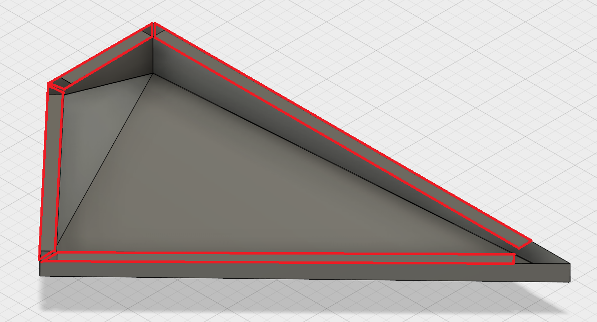
Fusion 360 folds 5 sheet metal flange commands base edge contour miter and swept into one flange command.

Fusion 360 sheet metal variable flange.

Let s show how to create sheet metal bends folds flange unfold flat pattern and more. Fusion automatically creates a flange starting from the modeled edge that follows the sketch contour. Design careers start with free fusion 360 software training no experience required. This must be done through command dialog box.

We just want to be able to get the job done. In the browser the part icon has changed to a sheet metal icon and the sheet metal rule appears below the document settings. Fusion 360 has released the sheet metal modeling environment. Share and vote on ideas for future product releases.

This article covers how to get started with sheet metal design in fusion 360. To make this design we will cover creating a base flange adding bends folding and unfolding the design virtually adding holes and other features and creating bending patterns that. In the model workspace you can normally convert bodies to components. Where there are breaks in the original edges the flange will automatically miter.

In this quick tutorial video synergis eds applications consultant dave breiner looks at the new bend feature within autodesk fusion 360 sheet metal. However a limitation is imposed for sheet metal bodies which prevents this action. Get free video training in fusion 360. The command is aware of what is being selected and will automatically switch to the right command.

The example part we will be designing is a bracket for the hitec hs 5065mg servo. To add additional edges make sure to hold control or command and the flange will adjust accordingly.

Solved Sheetmetal Autodesk Community Inventor

Solved Sheetmetal Autodesk Community Inventor

Solved Sheet Metal Flange Miter With Angle Autodesk Community Fusion 360

Solved Sheet Metal Flange Miter With Angle Autodesk Community Fusion 360

Inventor Sheet Metal Countour Flanges Youtube

Inventor Sheet Metal Countour Flanges Youtube

Multiple Flanges On Sheet Metal Face Autodesk Community Inventor

Multiple Flanges On Sheet Metal Face Autodesk Community Inventor

Source : pinterest.com